Samsung Scx-5835fn Training Manual.pdf 5v6ll
This document was ed by and they confirmed that they have the permission to share it. If you are author or own the copyright of this book, please report to us by using this report form. Report l4457
Overview 6h3y3j
& View Samsung Scx-5835fn Training Manual.pdf as PDF for free.
More details h6z72
- Words: 2,312
- Pages: 67
SCX-5835FN (Elbert-II) Training Manual Aug. 2008
MechanicalTechnical book Rev 0.1 1 / 67
Agenda I.
General Specification
II.
Process
III.
Disassembly
IV.
Troubleshooting
2 / 67
Ⅰ. General Specification
Objectives
Ⅰ. Understanding the General specifications of SCX-5835FN Ⅱ. Comprehension of the feature of major specs.
3 / 67
Ⅰ. General Specification
Overall Spec. Feature
SCX-5835FN
Size (WDH)
472x478x543mm
Weight (Net)
22.2 kg
Power Consumption
Printing mode
750 W
Power save mode
25 W
Power down mode
1W
Printing/Copy
52/54 db
Standby
39 db
Noise
4 / 67
Ⅰ. General Specification
Printing Printer Type
Mono - Laser Printing
Printing Speed
Simplex : 33 ppm (A4) / 35ppm (LTR) Duplex : 17 ipm (A4) / 18 ipm (LTR)
Resolution
1200dpi effective
Power save Mode
23.5 sec
Standby Mode
8.5 sec
FPOT
Warm up Time (Cold start)
Toner Cartridge
50 sec
Consumable
10K pages
In-box
4K pages 5 / 67
Ⅰ. General Specification
Scan Method
Color CCDM
Resolution
600 x 600 dpi (Optical)
Minimum Scan Line Time
0.73ms(Color) / 0.365(Mono)
Copy [ Simplex ] SDMC : 33m / MDSC : 29m Copying Speed (A4) [ Duplex ] 1-2 : 17ipm / 2-2 : 13ipm FCOT
9.5 sec - Platen 11.5 sec - DADF
Zoom Rate
25% ~ 400% - Platen 25% ~ 200% - DADF 6 / 67
Ⅰ. General Specification
Fax Modem Speed
33.6Kbps
Transmission Speed
App. 3.0 sec per page
Memory
80GB HDD
7 / 67
Ⅰ. General Specification
Paper Handling
Capacity (75gr/20 lb)
Main Tray
500 sheets (80gsm)
Manual Tray
50 sheets (80gsm)
Optional Tray
N/A 250 sheets (face-down) 1 sheet (face-up)
Capacity of Output Rear output tray is available for the special media such as envelope, label, postcard, transparency and so on.
8 / 67
Ⅰ. General Specification
Option Optional Feeder
500 sheets (80gsm)
Duplex Feeder (Factory option)
Letter, A4, Folio and Legal
Memory
Elbert2 provides one Extension Slot for extending Memory
9 / 67
Ⅱ. Process
Objectives Ⅰ. Comprehension of System Layout Ⅱ. Studying the printing process and electro-photographic process Ⅲ. Understanding the basic structures and operating principle of each parts
10 / 67
Ⅱ. Process 1. System Layout
DADF PART
ENGINE PART 11 / 67
Ⅱ. Process 2. Printing Process (General)
12 / 67
Ⅱ. Process
3. Mechanical Parts 3-1. Feeding Section Feeding type : Center Loading Cassette Type Feeding capacity : Main 500 Sheets (80gsm Standard Paper) MPF 50 Sheets (80gsm Standard Paper) / 5 Sheets (Special Media) Paper detecting sensor : Photo Interrupter
Cassette
MPF
13 / 67
Ⅱ. Process
3. Mechanical Parts 3-2. Transfer Roller Assy Looks similar to Elbert’s but different. Do not be confuse. (There is not Gear-Transfer for Elbert-II model.) Life span : 100,000 images
14 / 67
Ⅱ. Process
3. Mechanical Parts 3-3. Driver Assy Main motor ass’y (BLDC) : Paper Pickup, Paper Feeding, Toner Cartridge Exit motor ass’y (STEP) : F Unit, Letting out paper or Putting back paper Duplex motor ass’y (STEP) : Paper Transferring for duplex printing
Duplex Exit
Main
15 / 67
Ⅱ. Process
3. Mechanical Parts 3-4. F Assy 3-4-1. F Detail Fusing type : Thermal fixing with a couple of one heat roller and two pressure rollers Hear roller : ø28.3, Anodized, singel halogen lamp, thick brown color coating Pressure roller 1 : ø16.0 : PFA tube, Electrically conductive Pressure roller 2 : ø20.0 : LSR+PFA, Electrically conductive Single thermistor and a pair of thermostat A ball bearing at each end of heat roller (total amount; two) Jam removal lever / F door open for jam removal Life span : 80,000 pages
Thermistor
Thermostat
16 / 67
Ⅱ. Process
3-4-2. F Error
Error message is displayed. -Open Heat Error -Low Heat Error -Over Heat Error
“Over Heat Error“ Or “Low Heat Error”
Turn off the power and stay for 5minutes.
Turn on the printer.
Is the same message shown again?
No
OK
Yes End Samsung CC
SVC Engineer Replace the F Assy
Is the same message shown again?
Is the same message shown again?
Replace the SMPS
17 / 67
Replace the Main PBA
Ⅱ. Process
3-4-3. F Disassembly 1. Turn off the Printer and unplug the power cable. 2. Open the Rear Cover.
4. Unfold the Guide-Output (Black mold part).
3. Unfasten the strap.
4. Unscrew 4 screws on the F.
5. Check the F Assy whether defective or not (go to the next page)
18 / 67
Ⅱ. Process 3-4-4. Defective Checking • JC96-05064A : ELA UNIT-F 220V • JC96-05063A : ELA UNIT-F 110V
c
d
• 4712-001031 : THERMOSTAT • 1404-001364 : THERMISTOR-NTC ASSY
a
b
Thermostat (1)
(2) Halogen Lamp
Thermostat
1. Measure the resistance value between ⓐ and ⓑ - Defective : infinite - Non-defective : Approx. 0 (zero) ~ 1 ohm 2. If defective, replace the new thermostat. - Unscrews 2 screw ⓐ and ⓑ
1. Measure the resistance value between ⓒ and ⓓ - Defective : infinite - Non-defective : Approx. 0(zero) ~ 10 ohm 2. If defective, replace the new f ass’y
(3) Thermistor e
f
If you replace the thermistor , unscrew here
1. Measure the resistance value between ⓔ and ⓕ - Defective : infinite - Non-defective : Approx. 330 ~ 360 (K)ohm 2. If defective, replace the new thermistor. - Unscrews 1 screw.
※ Thermistor – Temperature-Measuring Device ※ Thermostat – Critical Temperature-Detecting Device
19 / 67
Ⅱ. Process
3. Mechanical Parts 3-5. LSU Laser diode : Dual type Same as Elbert Protecting glass for beam slot Safety inter-rock switch against beam emission while front cover open
20 / 67
Ⅱ. Process
3. Mechanical Parts 3-6. DADF Faster ADF than Elbert : 30 m/LTR (MDSP) Solenoid clutch Duplex Auto Document Feeder : Capacity 50 Sheets
Document Align : Center (with document guide)
21 / 67
Ⅱ. Process
3. Mechanical Parts 3-7. Flatbed Scanner Enhanced color CCD(Charge Coupled Device) : Kepler Middle with white LED light Minimum Scan Line Time: 0.73ms(Color) / 0.365(Mono) Scan Resolution : Optical 600 x 600 DPI
Color Depth : 36 Bits (Internal), 24Bits (External)
22 / 67
Ⅱ. Process
3. Mechanical Parts 3-8. OPE LCD : 7" Color LCD ( 800 by 480 line color TFT LCD )
23 / 67
Ⅱ. Process
3. Mechanical Parts 3-9-1. Toner Cartridge(1) Capacity : 4,000 images (in box) / 10,000 images (After-Market) [ ISO19752 pattern on A4 paper and 68°F (50 %) ~75 °F (60 %) ]
CRUM with encryption Non-magnetic 1 element ing method Toner: Non-magnetic 1 element shatter type toner (Average Dia. 8 ㎛ )
Frame- CR- Hol der PCB-CRUM Cl eani ng Bl ade
CR
Doctor Bl ade
Cap-Toner Frame- Cl eani ng
Drum OPC
DR
SR
Agi tat or1
Agi tat or2
Frame- Deve
24 / 67
Ⅱ. Process 3-9-2. Toner Cartridge(2) OPC Cleaning: Rake used toner into waste toner box with cleaning blade OPC Drum protecting Shutter : Do not have
OPC drive gear Cleaning blade
OPC drum Waste toner box OPC Drum (no protecting shutter)
Waste toner box
25 / 67
Ⅱ. Process 3-9-3. Toner Cartridge(3) Method of toner supply : Toner is transported to the developing roller by supply roller. Regulating toner level : SUS Blade (Doctor Blade)
Sus blade
Supply roller Developing roller
26 / 67
Ⅱ. Process 3-9-4. Components layout Toner Cartridge
CR cleaning CR
Upper Frame Doctor Blade
CRUM
Cleaning Blade Agitator1 Cleaning Frame
OPC
DR
SR
27 / 67
Agitator2
3-9-5. Applied voltage & measurement Gnd
Gnd
Gnd (-)1350V@NN
(-)390V
(-)590V
(-)1300 ~ (-)1450V
C/R D/R Voltage Measurement
D/R OPC
(+)1300V@NN
T/R
S/R Voltage Measurement 28 / 67
Gnd
(+)400 ~ 5000V
S/R
Ⅲ. Maintenance 3-9-6. Redistributing Toner
29 / 67
Ⅱ. Process
3. System Layout 3-10. Duplex Unit A4, Letter, Folio, Oficio and Legal Recommended to use heavier paper than 75gsm for duplex printing Standard
30 / 67
Ⅱ. Process
3. System Layout 3-11. Optional Feeder (SCF) Capacity : 500 sheets (80gsm) Available paper size : A5, Executive, JIS B5, ISO B5, A4(210x297mm), Letter(216x279mm), Legal, Folio, Oficio
31 / 67
Ⅱ. Process
4. Electrical Parts
32 / 67
Ⅱ. Process
4. Electrical Parts 4-1. Main Board
4-1. Main Board Scan MOTIC
Flash Memory
CHORUS3(ASIC) USB IC
DDR2 DIMM
Network IC
33 / 67
Ⅱ. Process
4. Electrical Parts
-2. Installing Printer Memory
34 / 67
Ⅱ. Process
4. Electrical Parts
-3. HVPS
SUPPLY -630±3% DEV -430±3%
THV +1300±3% -1200±3%
OPC -130±15.4% MHV -1350±3%
35 / 67
Ⅱ. Process
4. Electrical Parts
-4. SMPS
F
5V 24V
Fuse AC
36 / 67
Ⅱ. Process
4. Electrical Parts
-5. PBA-DRIVER
Exit motor
A3983SLP (Duplex motor)
Duplex motor A3983SLP (Exit motor)
Main Fan LSU Fan Duplex motor
SMPS
SMPS fan
→ SMPS Fan → Exit motor LSU fan
Exit motor / Duplex motor Main FAN / LSU FAN / SMPS FAN SMPS MAIN PBA
MAIN PBA
SMPS
→ main Fan
37 / 67
Ⅱ. Process
4. Electrical Parts DADF motor
P_size sensor
-6. PBA-DADF
→ Exit solenoid
A3983SLP
MAIN PBA
(DADF motor)
COVER OPEN sensor Regi solenoid
P_DET sensor
P_REGI sensor
P_POS sensor
→ Pick Up solenoid
DADF motor DADF P_POS / DADF P_REGI / DADF P_DET sensor DADF Cover OPEN / P_SIZE sensor DADF Exit solenoid / DADF Pick up solenoid 38 / 67
Ⅱ. Process
4. Electrical Parts
-7. PBA-OPE_MAIN OP_KEY_SUB
MAIN PBA
MAIN IF MAIN IF (POWER) (USB)
NOR FLASH 32MB
S3C2413C
OP_KEY_SUB
OP_KEY
LCD INTERFACE
TOUCH SCREEN BUZZER
LCD MAIN IF
BACK LIGHT
LCD BACK LIGHT IF LCD TOUCH IF
OP_KEY_SUB
DDR1 SDRAM 32MB
LCD OP_KEY_SUB / OP_KEY 39 / 67
DEBUG
JTAG
→ OP_KEY
Ⅱ. Process
4. Electrical Parts
-8. PBA-OPE_KEY_SUB
MAIN PBA
OPE_MAIN
OPE_MAIN USB2415-AEZG (USB HUB IC)
USB DIRECT
USB HUB IC(USB2415-AEZG) LEFT side KEY and LED of OPE -. LED : MACHINE STATUS GREEN and RED -. KEY : MACHINE SETUP KEY, JOB STATUS 40 / 67
Ⅱ. Process
4. Electrical Parts
OPE_MAIN
-9. PBA-OPE_KEY
RIGHT side KEY and LED of OPE -. LED : POWER SAVE / INTERRUP PRINTING -. KEY : INTERRUPT / CLEAR ALL / STOP CLEAR / ON HOOK / REDIAL-PAUSE / CLEAR / NUMBER 1 ~ 0 41 / 67
Ⅱ. Process
4. Electrical Parts
-10. PBA-FAX MAIN PBA
LINE SI2435 EXTERNAL
SiLAB modem
42 / 67
Ⅱ. Process
4. Electrical Parts
-11. PBA-SCF(Option) Paper empty sensor → MAIN PBA S3F443FX BLDC
solenoid
BLDC / Solenoid
Paper empty sensor
43 / 67
Ⅱ. Process
Review
Ⅰ. What is the function of paper feeding sensor ? Ⅱ. Do you know life span of Transfer Roller? Ⅲ. Do you know the function of Thermistor and Thermostat?
44 / 67
Ⅲ. Disassembly
Objectives
Ⅰ. Studying the method of disassemble parts from a complete whole Ⅱ. Comprehension of the function of each parts Ⅲ. Understanding the basic structures of major part
45 / 67
Ⅲ. Disassembly
46 / 67
Ⅲ. Disassembly
47 / 67
Ⅲ. Disassembly
48 / 67
Ⅲ. Disassembly
49 / 67
Ⅲ. Disassembly
50 / 67
Ⅲ. Disassembly
51 / 67
Ⅲ. Disassembly
52 / 67
Ⅲ. Disassembly
53 / 67
Ⅲ. Disassembly 5
5
54 / 67
Ⅲ. Disassembly
55 / 67
Ⅲ. Disassembly
56 / 67
Ⅲ. Disassembly
57 / 67
Ⅲ. Disassembly
1. Actual Training -. Refer to ‘Service Manual’ TBD
-. Refer to ‘Exploded view’ Adobe Acrobat Document
58 / 67
Ⅳ. Troubleshooting
Objectives
Ⅰ. Building ability to deal with various problems raised in the field by reviewing troubleshooting Ⅱ. Check the solution of each problem. Ⅲ. Check the difference of each Jam.
59 / 67
Ⅳ. Troubleshooting Clearing Jams in the Paper Tray Type
Case
Jam Removal
Jam 0
Leading edge of media does not 1. Pull out cassette arrive at registration within a certain 2. Remove jammed paper time after pick-up (If fails at a time,it tries pick-up again)
Jam 1
Leading edge of media does not 1. Open front cover arrive at Exit Sensor within a certain 2. Pull out toner cartridge time after registration 3. Remove jammed paper
Jam 2
Trailing edge of media does not leave Exit Sensor within a certain time after touching registration
1. Open rear cover (2. Pull down jam lever on f unit and open f cover) 3. Remove jammed paper from exit
60 / 67
Jam Layout
Ⅳ. Troubleshooting Clearing Jams in the Paper Tray
61 / 67
Ⅳ. Troubleshooting Clearing Jams in the Paper Tray
62 / 67
Ⅳ. Troubleshooting Clearing Jams in the Paper Tray
63 / 67
Ⅳ. Troubleshooting Clearing Jams in the D uplex Unit
Type
Case
Duplex Jam 1 Trailing edge of media leaves Exit Sensor, and does not arrive at Duplex Sensor
Jam Removal 1. Open rear cover 2. Remove jammed paper OR 1. Pull out duplex unit 2. Remove jammed paper from duplex unit
Duplex Jam 0 Leading edge of media does not 1. Open rear cover arrive at registration within a certain 2. Remove jammed paper time after touching Duplex Sensor OR 1. Pull out duplex unit 2. Remove jammed paper from duplex unit
64 / 67
Jam Layout
Ⅳ. Troubleshooting Clearing Jams in the D uplex Unit
65 / 67
Ⅳ. Troubleshooting Clearing Jams in the D A D F
Type Document Jam
Case All case of DADF Jam
Jam Removal 1. Open DADF open cover 2. Remove jammed paper OR 1. Open DADF open cover and Lift up DADF middle cover 2. Remove jammed paper
66 / 67
Ⅳ. Troubleshooting Clearing Jams in the D A D F
67 / 67
Related Documents 543cg
Samsung Plasma Training Manual 185x4s
December 2019 82
Samsung Bx2231 Bx2331 Bx2431 Training 6g3930
March 2023 0
Samsung Scx-6555n Training Manual.pdf 631l2w
December 2019 56
Samsung Oled Tv Training Guide.pdf 1vw3y
November 2021 0
Samsung Scx-5835fn Training Manual.pdf 5v6ll
December 2019 33
Samsung Rs275-rs277 - Refrigerator Training 2p725v
December 2019 30More Documents from "Da El" 1z1d73
Samsung Scx-6555n Training Manual.pdf 631l2w
December 2019 56
Samsung Oled Tv Training Guide.pdf 1vw3y
November 2021 0
Samsung Scx-5835fn Training Manual.pdf 5v6ll
December 2019 33
Samsung Ue48h6200 Chassis U8dc.pdf 5d2j46
November 2019 154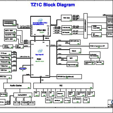
Quanta Tz1c Rev B2a- Toshiba Qosmio X505 1x6n5h
July 2021 0