What Is Huawei Quidway S5300 Gigabit Switches 506a5x
This document was ed by and they confirmed that they have the permission to share it. If you are author or own the copyright of this book, please report to us by using this report form. Report l4457
Overview 6h3y3j
& View What Is Huawei Quidway S5300 Gigabit Switches as PDF for free.
More details h6z72
- Words: 2,274
- Pages: 14
What is Huawei Quidway S5300 Gigabit Switches? Huawei S5300 switches are new generation Ethernet gigabit switches that meet the requirements for high-bandwidth access and Ethernet multi-service convergence, providing powerful Ethernet functions for operators and enterprise customers. Based on the new generation high-performance hardware and Huawei Versatile Routing Platform (VRP), the S5300 features large capacity and gigabit interfaces of high density, provides 10G uplinks, meeting the requirements for the 1G and 10G uplink devices of high density. The S5300 can meet the requirements of multiple scenarios such as service convergence on campus networks and Intranets, the access to the IDC at a rate of 1000 Mbit/s, and the access to computers at a rate of 1000 Mbit/s on Intranets.
Device Models Product Series
Model
Maximum Number of Interfaces
S5300C
S5328C-EI
28 There are twenty-four 10/100/1000BASE-T interfaces and four interfaces on the front subcard.
S5328C-EI-24S
28 There are twenty-four 100/1000BASE-X Ethernet optical interfaces, four GE combo interfaces (10/100/1000BASET+100/1000BASE-X, used together with the last four Ethernet interfaces), and four interfaces on the front subcard.
S5352C-EI
52 There are forty-eight 10/100/1000BASE-T interfaces and four interfaces on the front subcard.
Ethernet
28 There are twenty-four 10/100/1000BASE-T interfaces and four interfaces on the front subcard.
Ethernet
52 There are forty-eight 10/100/1000BASE-T interfaces and four interfaces on the front subcard.
Ethernet
S5328C-PWR-EI
S5352C-PWR-EI
S5328C-SI
1
Ethernet
28 There are twenty-four 10/100/1000BASE-T Ethernet interfaces, four GE combo interfaces (10/100/1000BASET+100/1000BASE-X, used together with the last four Ethernet interfaces), and four interfaces on the front subcard.
S5352C-SI
S5300TP
2
52 There are forty-eight 10/100/1000BASE-T interfaces and four interfaces on the front subcard.
Ethernet
S5328C-PWR-SI
28 There are twenty-four 10/100/1000BASE-T Ethernet interfaces, four GE combo interfaces (10/100/1000BASET+100/1000BASE-X, used together with the last four Ethernet interfaces), and four interfaces on the front subcard.
S5352C-PWR-SI
52 There are forty-eight 10/100/1000BASE-T interfaces and four interfaces on the front subcard.
Ethernet
S5328C-HI-24S
28 There are twenty-four 100/1000BASE-X Ethernet optical interfaces and four interfaces on the front subcard.
S5328C-HI
28 There are twenty-four 10/100/1000BASE-T interfaces and four interfaces on the front subcard.
Ethernet
S5324TP-SI
24 There are twenty-four 10/100/1000BASE-T Ethernet interfaces and four GE combo interfaces (10/100/1000BASET+100/1000BASE-X, used together with the last four Ethernet interfaces).
S5348TP-SI
48 There are forty-eight 10/100/1000BASE-T Ethernet interfaces and four GE combo interfaces (10/100/1000BASET+100/1000BASE-X, used together with the last four Ethernet interfaces).
S5324TP-PWR-SI
24 There are twenty-four 10/100/1000BASE-T Ethernet interfaces and four GE combo interfaces (10/100/1000BASET+100/1000BASE-X, used together with the last four Ethernet interfaces).
S5348TP-PWR-SI
48 There are forty-eight 10/100/1000BASE-T Ethernet interfaces and four GE combo interfaces (10/100/1000BASET+100/1000BASE-X, used together with the last four Ethernet interfaces).
S5306TP-LI-AC
6 There are four 10/100/1000BASE-T Ethernet interfaces and two GE combo interfaces (10/100/1000BASET+100/1000BASE-X).
Naming Rules Naming rules of the S5348TP-PWR-SI, S5328C-EI-24S, S5328C-HI, and S5306TPLI-AC.
3
Identifier
Description
A
Product brand.
B
Switch
C
Product series. "53" indicates the S5300 series.
D
Maximum number of interfaces. NOTE: The number of interfaces on an S5300 can be 6, 24, 28, 48, or 52, depending on the device model.
E
Uplink interface type: C: A device s interface cards. There can be two or four uplink interfaces on an interface subcard. TP: A device has combo interfaces ing optical and electrical interfaces.
F
The S5300 s Power over Ethernet (PoE). NOTE: If this letter is not displayed, PoE is not ed.
G
Software version type: EI: enhanced version, ing enhanced features
SI: standard version, ing basic features HI: advanced version, ing high-performance Operation, istration, and Maintenance (OAM) and built-in real-time clock (RTC) LI: simplified version
H
Downlink interface type. The value 24S indicates that 24 downlink interfaces of the S5328C-EI-24S are optical interfaces. NOTE: If this letter is not displayed, all downlink interfaces are electrical interfaces.
I
Powering mode: AC: alternating current power DC: direct current power
Huawei S5300 Controller Subrack Appearance of the S5300 controller subrack
The S5300 controller subrack uses the modular structure and consists of the following components: System subrack Front part of the controller subrack 1. 4
Hard disk module
Rear part of the controller subrack 2. 3. 4. 5.
Two AC PEM/fan modules or two DC PEM/fan modules Two battery modules (AC PEM/fan modules) or two baffles (DC PEM/fan modules) Two controllers One DIP switch board
NOTE: Disk modules, power-fan modules, and controllers are FRUs. The S5300 controller subrack s AC or DC power supply. You can select PEM/fan modules (AC PEM/fan modules or DC PEM/fan modules) as required Structure of the S5300 controller subrack configured with AC PEM/fan modules
1 System subrack
2 Hard disk module
3 AC PEM/fan module
4 Battery module
5 Controller
6 DIP switch board
5
System Subrack The system subrack provides the following functions: The system subrack can integrate all modules into one environment. The wind channels and holes in the system subrack ensure heat dissipation for all modules. The shielding function of the system subrack prevents electromagnetic radiation inside and outside the controller subrack.
Hard Disk Module The S5300 controller subrack s hard disks of the following specifications: SSD hard disks with the capacity of 73 GB or 200 GB. FC hard disks with the capacity of 300 GB, 450 GB or 600 GB, and the rotational speed of 15000 r/min. SATA hard disks with the capacity of 500 GB, 1 TB or 2 TB, and the rotational speed of 7200 r/min. NOTE: To save storage space and obtain better performance, you are recommended to use hard disks with the same capacity and rotational speed for a RAID group. The FC hard disk module consists of a disk handle, hard disk tray and FC hard disk. FC hard disk module
1
6
Hard disk handle
2
Hard disk tray
3
FC hard disk
The SATA hard disk module consists of a disk handle, hard disk tray, and SATA hard disk, SATA conversion board. SATA hard disk module
1
Hard disk handle
2
Hard disk tray
3
SATA hard disk
4
SATA conversion board
NOTE: SATA conversion board is the board that converts the SATA interface into the FC interface. The FC hard disk module consists of a disk handle, hard disk tray, SSD hard disk and bracket. SSD hard disk module
1 Disk handle 7
2 Hard disk tray
3 SSD hard disk
4 Bracket
The hard disk module is primarily used to provide the storage capacity for the system, and the hard disks in the coffer also provides the following functions: Storing system configuration data The system configuration data is stored on the coffer of the controller subrack, that is, the hard disks in slots 0 to 3. Saving write cache data when the system input power supply fails When a power failure occurs, the battery starts to supply power to the controller subrack. Meanwhile, the system writes the data in the cache to the coffer within two minutes. Providing the storage capacity The controller subrack stores the system data in the coffer and uses the remaining capacity for storage. CAUTION: The coffer hard disks in slots 0 to 3 of the controller subrack save the critical system data. In addition, a hard disk must be present in slot 0 or slot 1, and another hard disk must be present in slot 2 or slot 3. Do not insert or remove a hard disk randomly, or change the sequence of the hard disks in the coffer. Otherwise, system data might be damaged. In the controller subrack, the hard disk modules are numbered from left to right and from top to bottom according to slot numbers. The 24 slots are numbered from 0 to 23. Slot 0 is located on the upper left of the controller subrack. Locations of slots 0 to 3 in the controller subrack
8
The yellow labels are the warning labels for removing or inserting the coffer disks.
PEM/Fan Module CAUTION: The controller subrack needs to be equipped with PEM/fan module of the same manufacturer and the same software version. PEM/fan module in the S5300 controller subrack are classified into the following types: AC PEM/fan module DC PEM/fan module Rear view of the AC PEM/fan module
1 Power switch
2 Power running indicator
3 Power alarm indicator
4 Fan alarm indicator
5 Power socket
6 Fan
Rear view of the AC PEM/fan module
9
1 Power switch
2 Power running indicator
3 Power alarm indicator
4 Fan alarm indicator
5 Power socket
6 Fan
The S5300 controller subrack is equipped with two PEM/fan modules. Two PEM/fan modules constitute a 1+1 load-balancing power system. One PEM/fan module enables the controller subrack to work normally in maximum power consumption mode. The PEM/fan modules hot swapping. When one PEM/fan module fails, the entire system is not affected. Based on the types of the input power supplies, the PEM/fan modules in the S5300 controller subrack can be classified into the two types: AC PEM/fan module The input power ranges from 200 V to 240 V AC, when the AC power is supplied in the equipment. DC PEM/fan module The input power ranges from -48 V to -60 V DC, when the DC power is supplied in the equipment room. The PEM/fan module of the S5300 controller subrack provides the following functions: Supplying power to the system in the case of 200V to 240V AC or -60V to -48V DC input When one power supply fails, the power supply system is not affected. Heat dissipation Either PEM/fan module of the controller subrack is integrated with two fan modules (non-FRU) that can be replaced separately. When the system runs normally, 10
the four fans of the two PEM/fan modules run simultaneously for cooling the controller subrack. Any fan failure in the two PEM/fan modules does not affect heat dissipation.
Battery Module NOTE: Only the system that s the AC power supply with battery management is configured with batteries. Each controller subrack is equipped with two battery modules Battery module
1 Battery running indicator 2 Battery discharge indicator 3 Battery alarm indicator The battery module provides the following functions: When power failure occurs, it can use the battery to supply power to the controller subrack for at least two minutes. In this way, the data in the write cache of the controller can be written to the coffer to avoid data loss.
Controller The S5300 controller subrack is configured with two controllers. The controllers flexibly configure FC ports modules or iSCSI port modules to form various SAN. 11
There are two types of configurations: When all FC port modules are configured with the controllers, the FC SAN can be formed. Controller configured with two FC port modules
1
FC port module
2
FC host port
3
Subrack ID diaplay
4
Controller handle
5
COM 0 serial port
6
Management network port active indicator
7
Management network port
8
Management network port link indicator
9
FC expander port
10 COM 1 serial port
11
Controller alarm indicator
12 Controller power indicator
When one controller is configured with an FC host port module and an iSCSI host port module, the FC SAN and the IP SAN can be formed at the same time. Controller configured with an FC port module and an iSCSI port module
12
1
FC port module
2
FC host port
3
iSCSI port module
4
iSCSI host port
The controller provides the following functions: Handling storage services The controller receives a read-and-write small computer system interface (SCSI) command from the front-end host port. It runs the command, and then returns the result to the AS. Receiving configuration and management commands and saving configurations The controller configures the storage service through Web UI or CLI. Connecting SATA, SSD or FChard disks The controller connects the SATA, SSD or FC in the controller subrack and disk subrack to the S5300 storage system. Generating alarms and logs, and saving them in the local coffer
DIP Switch Board The DIP switch board provides the following functions: Adjusting the rear loop rate to 2 Gbit/s or 4 Gbit/s Resetting the buzzer NOTE: It is suggested to adjust the speed before system is powered on. If you adjust the speed after system power on, the corresponding rate indicator will be on but the adjustment does not take effect. You must power off and then restart the controller subrack. After changing the rate of the controller subrack, you must also change the rate of the disk subracks. By default, the buzzer of the S5300 controller subrack is closed. DIP switch board
1 Buzzer mute button 2 2 Gbit/s indicator 3 4 Gbit/s indicator 4 Rate switch More related topics The Basic Knowledge of Switches Naming Conventions of Huawei Parts 13
Huawei 5300 switch basic configuration Huawei S5300 Gigabit Switches Overview Huawei S2300 vs S3300 vs S5300 vs S9300 More Huawei products and Reviews you can visit: http://www.huanetwork.com/blog
Huanetwork.com is a world leading Huawei networking products supplier, we supply original new Huawei networking equipments, including Huawei switches, Huawei routers, Huaweisymantec security products, Huawei IAD, Huawei SFP and other Huawei networking products. Our customers include telecom operators, Huawei resellers, ISP and system integrators. Right now most of our sales are contributed by regular customers. In Huanetwork Lab, also we have Huawei OLT, MDU, DSLAM and switch for customer do remote testing, any potential customer are welcome to to our lab. If you need a total Huawei FTTx solution or Huawei ADSL solution for your network, also you may feel free to us.
Our website: http://www.huanetwork.com Telephone: +852-30501940 Email: [email protected] Address: 23/F Lucky Plaza, 315-321 Lockhart Road, Wanchai, Hongkong
14
Related Documents 543cg

What Is Huawei Quidway S5300 Gigabit Switches 506a5x
December 2021 0
What Is Huawei 1z1o4p
July 2022 0
Huawei S5300 Datasheet 2i6i5h
January 2022 0
Quidway S3900 Series Ethernet Switches Installation Manual 394638
November 2019 31
Quidway S5600 Series Ethernet Switches Operation Manual-release 1510 3r1f4q
July 2021 0
Quidway S3000-ei Series Ethernet Switches Command Manual(v1.04) 6s2j6b
August 2021 0More Documents from "Elizabeth Rich" 5p2c6b
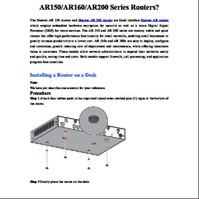
How To Install Huawei Ar150-ar160-ar200 Series Routers 5t4o6a
November 2019 58
How To Configure Huawei Router-on-a-stick 2v1x6u
November 2019 146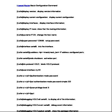
Huawei Router Basic Configuration Command 383d5g
November 2019 208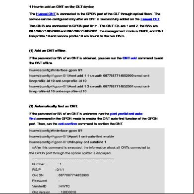
How To Add And Delete Ont On The Olt Device 2a4m1e
November 2019 86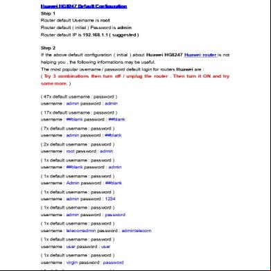
Huawei Hg8247 Huawei Router Default Configuration 1q4i3k
November 2019 74