Service And Parts Manual Rexel Shredder 1350-3250 Heavy Duty 5t4g6y
This document was ed by and they confirmed that they have the permission to share it. If you are author or own the copyright of this book, please report to us by using this report form. Report l4457
Overview 6h3y3j
& View Service And Parts Manual Rexel Shredder 1350-3250 Heavy Duty as PDF for free.
More details h6z72
- Words: 7,649
- Pages: 50
HEAVY DUTY SERIES 7 SHREDDERS – 230V ILLUSTRATED PARTS LISTS AND SERVICE INSTRUCTIONS Compiled by David Bird Approved by Paul Aries
Issue No 7 (Technical Manager)
Date 10/05/02
ILLUSTRATED PARTS MANUALS SERIES 7 SHREDDERS – 230V HEAVY DUTY
TABLE OF CONTENTS ILLUSTRATED PARTS MANUAL HEAVY DUTY SERIES 7 SHREDDERS – 230 VOLTS
Preface
Page 3
Illustrations and Parts Lists with Recommended Spares
Pages 4 – 16
CUTTING HEADS Model 1350 S2, 3250 S2-4 and 3250 S2-6
Pages 4 - 6
Model 1350 S3, 3250 S3
Pages 7 - 8
Model 3250 S4
Pages 9 - 11
CABINETS Models 1350, 3250
Pages 12 - 14
ELECTRICAL
Heavy Duty2 Issue No 7
Models 1350
Page 15
Models 3250
Page 16
1 15/05/02
ILLUSTRATED PARTS MANUALS SERIES 7 SHREDDERS – 230V HEAVY DUTY
SERVICE INSTRUCTIONS
Pages 17 – 48
Operational test procedures
Page 17
1. Top Cover
Pages 18 – 20
2. Cutting heads
Page 21
3. Printed Circuit Boards
Page 22
4. Auto-start Sensors
Page 23
5. Drive Belts
Page 24
6. Electric Motors
Pages 25 – 27
7. Gears
Pages 28 – 30
8. Tie Bars, Cutting Shafts, Paper Feed – Straight Cuts.
Pages 31 – 32
9. Tie Bars, Cutters, Strippers, Shafts - Cross Cuts.
Pages 33 – 36
10. LCD Operation
Pages 37 – 39
WIRING DIAGRAM
Pages 40 – 42
Model 1350 S2 and 1350 S3
Page 40
Model 3250 S2-4 and 3250 S2-6
Page 41
Model 3250 S3 and 3250 S4
Page 42
SPECIFICATIONS
Pages 43 - 48
AMENDMENT SHEET
Page 49
Heavy Duty2 Issue No 7
2 15/05/02
ILLUSTRATED PARTS MANUALS SERIES 7 SHREDDERS – 230V HEAVY DUTY
PREFACE This manual provides the instructions for the replacement of all the components that may become worn or damaged. Details of replacement parts and ordering information are given in associated illustrated parts list. For operating instructions see OI-513-06-97 for 1350 range and OI-514-06-97 for 3250 range. Illustrated Parts Lists For each machine, these give full details of the replacement part numbers with ing diagrams to show the location of the components.
Service Instructions For each machine, these give the recommended servicing procedure with ing pictorial diagrams for added clarity and applies from the following serial Nos 1350 S2 3250 S2-4 3250 S3
A631620 A646971 A630160
1350 S3 3250 S2-6 3250 S4
A640181 A629296 A630150
WARNING 1. Check the machine RATING PLATE DETAILS are compatible with the electrical mains supply. 2. Disconnect the electrical mains supply before removing any covers. 3. After removing the cover on single phase machines, DISCHARGE the capacitor by shorting out its
connections. (BEWARE: PAPER DUST IS A POTENTIAL FIRE HAZARD). 4. The machine MUST have a sound Electrical Earth connection.
NOTE:
Heavy Duty2 Issue No 7
THE ELECTRIC MOTOR IS PROTECTED BY AN AUTOMATIC THERMAL OVERLOAD CUT-OUT.
3 15/05/02
ILLUSTRATED PARTS MANUALS SERIES 7 SHREDDERS – 230V HEAVY DUTY MODEL 1350 S2, 3250 S2-4 and 3250 S2-6 CUTTING HEAD No 1 1 2 3 4 5 6 7 8 9 10 11 12 13 14 15 16 17 18 19 20 21 21 22 23 24 25 26 27 28 29 30 31 32 33 33 34 35 36 37 38 39 40 41 41 42 43 44
Description Side Frame (Motor) Side Frame (Motor) Pin, 20MM long, 5mm dia 1-1 Gear Circlip, 17MM ID Lost Motion Collar Spur Gear Assembly Gearbox Spacer Dowel Pin End Closing Plate Bolt, M5 x 70MM Ball Bearing Ball Bearing Compound Gear Assembly Screw, M5 x 12 CSK Nyloc Screw, M5 x 10 Lockwasher, M5 Locknut, M5 Torsion Spring (Motor Side) Torsion Spring Bearing Side Trigger Arm Bolt, M5 x 30 Motor, 150W Motor, 550W Screw, M6 x 12 Lockwasher, ¼” Tie Bar (Top Motor) Motor Bracket Motor Fan Grommet, Blind Cover Brace Active Safety Flap Bin Full Flap Grommet Location Plate Side Frame (Bearing) Side Frame (Bearing) Grommet Snap Bush Pop Rivet Nut M6 Washer, ¼” Plain Vibration Isolator Nut cover Cutter Shaft Driven Cutter Shaft Driven Tie Bar Key, 5X5X16 Stripper Plate – Front
Heavy Duty2 Issue No 7
Part D54220 D54221 PEG77 D53515 TRU88 D53790 A53650 D53520 PEG91 D54111 SCM151 BR23 BR28 A53547 SCM152 SCM9 SHK10 NM16 D53524 D53525 D53523 SCM140 SL20-301 SL20-307 SCM38 SHK11 D54036 D54119 SL18-140 D54062 A54023 D54114 SL18-333 D54018 D54083 D54076 GRM22 SL18-369 RTS68 NM5 PLN4 SL18-305 SL18-325 D54000 D54005 D54004 KEY32 D54016
4 15/05/02
1350 S2 1
3250 S2-4
3250 S2-6
1 2 2 1 1 1 1 6 1 5 5 2 1 2 4 4 2 1 1 2 2
1 2 2 1 1 1 1 6 1 5 5 2 1 2 4 4 2 1 1 2 2
1 6 6 1 1 2 5 1 1 1 2 2
1 6 6 1 1 2 5 1 1 1 2 2
2 2 4 8 8 4 2
1 2 2 4 8 8 4 2
1 2 2 4 8 8 4 2 1
1 2 2
1 2 2
2 2 1 1 1 1 6 1 5 5 2 1 2 4 4 2 1 1 2 2 1 6 6 1 1 2 5 1 1 1 2 2 1
2 2 1
Comments
Not Shown
Supplied with Motor
ILLUSTRATED PARTS MANUALS SERIES 7 SHREDDERS – 230V HEAVY DUTY
No 44 45 46 46 47 47 48 49 49
Description Stripper Plate – Front Deflector Tab Stripper Plate – Rear Stripper Plate – Rear Cutter Shaft – Drive Cutter Shaft Drive Key ‘Woodruff’ 5 x 9 x 22 Safety Flap Location plate Safety Flap Location plate End Plate Assembly Gearbox Spacer Assembly Side Frame Assembly (Motor) Side Frame Assembly (Motor) Side Frame Assembly (Bearing) Side Frame Assembly (Bearing) Head Assembly
Part D54003 D53641 D54017 D54002 D54001 D54006 KEY33 D54049 D54152 A54112SP A53531SP A54226SP
Head Assembly
A54031SP
Head Assembly
A54032SP
Shredder Oil, 500 ML
40100
Heavy Duty2 Issue No 7
1350 S2 1 2
3250S2-4 1 2
1
1
1 1 3
1 1 2 1 1 1
1 1 2 1 1
1
1
1 1 1
COMPRISES 9,11,12 COMPRISES 7,8 COMPRISES 1,11,32,12 COMPRISES 1,11,32,12 COMPRISES 33,32,11
1
1
1 1 1 1
5 15/05/02
2 1
1
A54078SP A54029SP
Comments
1
A54227SP A54085SP
3250 S2-6
1
1
COMPRISES 33,32,11 COMPRISES ALL EXCEPT 21,25,26,34,35,14 COMPRISES ALL EXCEPT 21,25,26,34,35,14 COMPRISES ALL EXCEPT 21,25,26,34,35,14
ILLUSTRATED PARTS MANUALS SERIES 7 SHREDDERS – 230V HEAVY DUTY MODEL 1350 S2, 3250 S2-4 and 3250 S2-6 Cutting Head
Heavy Duty230v Issue No 3
6
16/08/99
ILLUSTRATED PARTS MANUALS SERIES 7 SHREDDERS – 230V HEAVY DUTY Model 1350 S3 and 3250 S3 Cutting Head No 1 5 6 7 8 9 10 11 12 13 13 14 15 16 17 17 18 19 20 21 22 23 24 24 25 26 27 28 29 30 31 32
33 34 34 35 36 37 38
Description Driven Shaft Key Front Infeed chute Deflector Tab Drive shaft
Part D54139 KEY31 D54101 D54137 D54138
1350 S3 1 2 1 2 1
3250 S3 1 2 1 2 1
Stripper location plate Gearcase 33 tooth gear Side frame motor Side frame motor Compression Spring Shoulder Spacer Screw M8 x 35mm Hex Spring Actuating plate Spring Actuating plate Screw M8 x 30mm Hex Spacing collar Plain washer Shakeproof washer M8 Nyloc Nut M8 Gearbox complete Drive belt Drive belt Gear casing circlip Tie rod (Gearbox) Torsion Spring (Motor side) Torsion Spring (Bearing side) Trigger Arm Bolt M5 x 30 Motor bush Tie Rod (short) M8 Screw (motor) – Hex M5 Screw C’sunk nyloc M5 screw Hex head M8 Shakeproof washer M5 Shakeproof washer Motor pulley Motor pulley Socket set screw M5 600W motor 300W Motor M8 Screw Hex M8 Shakeproof Washer
D54149 45509 26010 D54091 D54109 D54230 D54231 SCM166 D54095 D54133 SCM59 45539BI PLN5/L SHK5 NM22 45667 SL22-82 SL22-88 TRU84 D54129 D53524 D53525 D53523 SCM140 45535 D54161 SCM38 SCM152 SCM9 SHK6 SHK10 45621 44753 SCM27 SL20-309 SL20-305 SCM38 SHK5
1 1 1
1 1 1 1
Comments
Not used
Heavy Duty230v Issue No 3
1 1 1 1 1
Not shown Not shown Not shown
1
1 1 1 1 1 1 2 2 2
1 1 1 1 1 1 1 1 1 1 1 2 2 2 2 4
(Not shown)
2 2 4 2 1 1 1 1 12 12
7
1 1 12 12
16/08/99
ILLUSTRATED PARTS MANUALS SERIES 7 SHREDDERS – 230V HEAVY DUTY
No 39 40 41 42 43 44 45 46 47 48 49 50 51 52 53 54 55 56 57 58 59 60 61 64
Description Tie bar (Long) Motor bracket M6 C’sunk socket head M6 C’sunk shakeproof washer Motor fan Grommet, blind Cover bracing plate Active safety flap Bin full flap Grommet Rear infeed chute Ball bearing (modified) Safety flap location plate Bearing side frame Grommet Snap Bush Nut M6 Washer ¼ plain Washer ¼ shakeproof Vibration Isolator Nut cover Location plate Circlip Stripper Paper chute Stripper location plate assembly Side frame assembly (Bearing) Head Assembly
Part D54098 D54119 SCM156 SHK13
1350 S3 3 1 2 2 2 5 1 1 1 2 1 4 2 1 1 2 8 8 8 4 2 1 2 236 1 1
3250 S3 3
Comments
1 5 1 1 1 2 1 4 2 1 1 2 8 8 8 4 2 1 2 236 1 1
Supplied with motor
A54169SP A54033SP
1
1 1
Head Assembly
A54030SP
1
Comprises 50,52,59 Comprises all except 32,33,36,40,43,53,54 Comprises all except 32,33,36,40,43,53,54
Shredder oil 500ml
40100
1
Heavy Duty2 Issue No 7
SL18-140 D54107 A54023 D54103 SL18-333 D54102 D54059 D54106 D54090 GRM22 SL18-369 NM5 PLN4 SHK4 SL18-305 SL18-325 D54094 TRU97 D54142 D54100 A54170SP
8 15/05/02
1
2 on RH side frame
Comprises 10,11,50
ILLUSTRATED PARTS MANUALS SERIES 7 SHREDDERS – 230V HEAVY DUTY
Model 3250 S4 Cutting Head No 1 2 3 4 5 6 7 8 9 10 11 12 13 14 15 16 17 18 19 20 21 22 23 24 25 26 27 28 29 30 31 32 33 34 35 36 37 38 39 43 44 45 46 47 48 49 50 51
Description Driven Shaft Stripper retaining collar Lock washer Locknut Key Front Infeed chute Deflector Tab Drive shaft
Part D54105 D54045 TAB1 NM20 KEY31 D54101 D54137 D54104
3250 S4 1
Stripper location plate Gearcase 33 tooth gear Side frame motor Compression Spring Shoulder Spacer Screw M8 x 35mm Hex Spring Actuating plate Screw M8 x 30mm Hex Spacing collar Plain washer Shakeproof washer M8 Nyloc Nut M8 Gearbox complete Drive belt Gear casing circlip Tie rod (Gearbox) Torsion Spring (Motor side) Torsion Spring (Bearing side) Trigger Arm Bolt M5 x 30 Motor bush Tie Rod (short) M8 Screw (motor) – Hex M8 Shakeproof washer Motor pulley Socket set screw M5 600W motor M8 Screw Hex M8 Shakeproof Washer Tie bar (Long) Motor fan Grommet, blind Cover bracing plate Active safety flap Bin Full flap Grommet Rear infeed chute Ball bearing (modified) Safety flap location plate
D54149 45509 26010 D54091 D54230 D54231 SCM166 D54095 SCM59 45539BI PLN5/L SHK11 NM22 45667 SL22-82 TRU84 D54129 D53524 D53525 D53523 SCM140 45535 D54099 SCM38 SHK11 45621 SCM27 SL20-309 SCM38 SHK5 D54098
1 1 1 1 1 1 1 1 1 1 1 1 1 1 1 1 1 1 1 2 2 2 2 4 4 1 1 1 12 12 3 1 5 1 1 1 2 1 4 2
Comments
2 2 2 1 2 1 Not used
Heavy Duty2 Issue No 7
SL18-140 D54107 A54023 D54136 SL18-333 D54102 D54059 D54106
9 15/05/02
Not shown Not shown Not shown
(Not shown)
Supplied with motor
2 on RH side frame
ILLUSTRATED PARTS MANUALS SERIES 7 SHREDDERS – 230V HEAVY DUTY
No 52 53 54 55 56 57 58 59 60 61 62 63 64
Description Bearing side frame Grommet Snap Bush Nut M6 Washer ¼ plain Washer ¼ shakeproof Vibration Isolator Nut cover Location plate Circlip Stripper Cutter spacer Cutter Paper chute Stripper location plate assembly Side frame assembly (bearing) Head Assembly Shredder oil 500ml
Heavy Duty2 Issue No 7
Part D54150 GRM22 SL18-369 NM5 PLN4 SHK4 SL18-305 SL18-325 D54094 TRU97 D54097 26012 D41620 D54100 A54170SP A54171SP A54034SP 40100
3250 S4 1 1 2 8 8 8 4 2 1 2 264 266 268 1 1 1 1
10 15/05/02
Comments
Comprises 10,11,50 Comprises 50, 52, 59 Comprises all except 32,33,36,40,41,42,43,53,54
ILLUSTRATED PARTS MANUALS SERIES 7 SHREDDERS – 230V HEAVY DUTY
MODEL 1350 S3, 3250 S3 and 3250 S4CUTTING HEAD
Heavy Duty230v Issue No 3
11
16/08/99
ILLUSTRATED PARTS MANUALS SERIES 7 SHREDDERS – 230V HEAVY DUTY MODEL 1350 S2 AND 1350 S3 CABINET No 1 2 5 5 6 7 7a 7b 8 8a 9 10 11 12 13 13a 14 15 16 17 18 19 20 21 22 23 24 25 26 27 28
29 30
Description Door Assembly Door Handle Cabinet Assembly Cabinet Assembly Screw M4 x 12 Csk Top cover assembly Top cover assembly Decal Rexel LED Blank LED Decal Forward Button Reverse Button Stop button Screw No 8 Pozi Pan Plas No 8 Plastic Bin Plastic Bin Handle Door Catch, Magnetic Washer, M8 Flat Washer M8 Shakeproof
Part A54184 D54140 D54188 D54189 SCM81 A54153 A54154 D000402 D53505 D000396 D53506 D53504 D53503 SCR707
1350 S2 1 1 1
1 1 1 1 1 1 3
1 1 1 1 1 1 1 3
D54229 D53820C SL23-12 PLN5/L SHK11
1 2 1 4 4
1 2 1 4 4
Castor Door spacer Door Hinge (Bottom) Bracket Screw, M4 x 25 Washer M4 Shakeproof Hinge plate Fused Inlet Socket. Fuse Front castor restraint. Power Bulge Screw No 6 x ¼ Door Assy (spares) Cabinet Assy (spares) Cabinet Assy (spares) Cable Inlet Plate Rivet Door Switch
SL18-259 SL18-245 D53540
4 1 1
4 1 1
SCM25 SHK2 45610BI SL12-51 SL15-22 D54135 D54113 SCR543 A54184SP A54188SP A54189SP D54176 RTS72
2 2 1 1 1 2
2 2 1 1 1 2 1 4 1
3 1
1350 S3 1 1
Comments
1 3 LED Blank, decal and model number decal. LED Blank, decal and model number decal.
Not used
Heavy Duty230v Issue No 3
1 1 1 4
Not shown Not shown Not shown
1 1 4 See Electrics
12
16/08/99
ILLUSTRATED PARTS MANUALS SERIES 7 SHREDDERS – 230V HEAVY DUTY
MODELS 3250 CABINET No 1 2 5 5 6 7 7a 7b 8 8a 9 10 11 12 13 13a 14 15 16 17 18 19 20 21 22 23 24 24 26 27 28
29 29 30
Description Door Assembly Door Handle Cabinet Assembly Cabinet Assembly Screw M4 x 12 Csk Top cover assembly Top cover assembly Decal Rexel LCD Lens LCD Gasket Forward Button Reverse Button Stop button Screw No 8 Pozi Pan Plas No 8 Plastic Bin Plastic Bin Handle Door Catch, Magnetic Washer, M8 Flat Washer M8 Shakeproof
Part A54184 D54140 A54188 A54189 SCM81 A54155 A54156 D000403 D53507 D53640 D53506 D53504 D53503 SCR707
3250 S2-4 1 1 1
3250 S2-6 1 1 1
3250 S3 1 1
3250 S4 1 1
3 1
3 1
1 3
1 3
1 1 1 1 1 1 3
1 1 1 1 1 1 1 3
1 1 1 1 1 1 1 3
1 1 1 1 1 1 3
D54229 D53820C SL23-12 PLN5/L SHK11
1 2 1 4 4
1 2 1 4 4
1 2 1 4 4
1 2 1 4 4
Castor Door spacer Door Hinge (Bottom) Bracket Screw, M4 x 25 Washer M4 Shakeproof Hinge plate Fused inlet socket Inlet Socket Castor restraint Power Bulge Screw No 6 x ¼ Door Assy (spares) Cabinet Assy (spares) Cabinet Assy (spares) Cable Inlet Plate Cable Inlet Plate Door Switch
SL18-259 SL18-245 D53540
4 1 1
4 1 1
4 1 1
4 1 1
SCM25 SHK2 45610BI SL12-51 SL12-47 D54135 D54113 SCR543 A54184SP A54188SP A54189SP D54176 D54215
2 2 1 1
2 2 1 1
2
2
1 1
1 1
2 2 1 1 1 2 1 4 1
2 2 1 1 1 2 1 4 1
1
1
1 1 1
1 1 1
Comments
Including LCD Lens and Gasket Including LCD Lens and Gasket
Not used
Heavy Duty2 Issue No 7
Not shown Not shown
See Electrical
13
15/05/02
ILLUSTRATED PARTS MANUALS SERIES 7 SHREDDERS – 230V HEAVY DUTY
MODEL 1350/3250 CABINET
Heavy Duty2 Issue No 7
14
15/05/02
ILLUSTRATED PARTS MANUALS SERIES 7 SHREDDERS – 230V HEAVY DUTY
MODELS 1350 ELECTRICS No
Description Capacitor 12 µFD Capacitor 15 µFD Cord Set UK Cord Set – Euro Fuse 10A Screw Brass 2Ba Locknut, Brass Lockwasher Washer Brass 2 Ba Plain Micro switch Micro switch Micro switch Microswitch Insulation Nut M3 Nyloc Control PCB assembly with Auto start sensors Screw M3 x 16 Screw M3 x 8 Pozi pan plasform Washer M3 plain Wiring Loom Wiring Loom Wiring Loom Wiring Loom Wiring Loom Wiring Loom
Heavy Duty2 Issue No 7
Part SL6-41 SL6-53 SL4-88 SL4-90 SL15-22 SCR686B Nut42B SHK2 PLN3B SL8-167 SL8-164 SL8-165 D53545 NM14 SL17-305
1350 S2 1 1 1 1 1 2 2 2 1 2 2 1 8 1
1 1 1 1 1 2 2 2 1 2 2 1 8 1
SCM78 SCR713
6 7
6 7
For Inlet socket Earth stud For earth stud For earth stud For earth stud Bin Full switch For safety flap Door switch (Spares use A53548SP) For Bin Full Switch For limit switches & sensors For 1350S3 model. Change JP1 setting from J1 to J2 For limit switches To fix PCB assembly
PLN31 A54222 A54223 A53835 D53760 D53776 D53832
8 1 1 1 1 1 1
8 1 1 1 1 1 1
For limit switches & sensors Main Loom Link Loom Safety Circuit Loom Earth Wire Door Switch General Interconnection
15
1350 S3
Comments For motor start For motor start
15/05/02
ILLUSTRATED PARTS MANUALS SERIES 7 SHREDDERS – 230V HEAVY DUTY MODELS 3250 ELECTRICS No
Description
Part
Capacitor 30 µFD Capacitor 15 µFD Cord Set UK Cord Set Euro Fuse 10A Circuit Breaker Screw Brass 2Ba Locknut, Brass Lockwasher Washer Brass 2 Ba Plain Micro switch Micro switch Micro switch Microswitch Insulation Nut M3 Nyloc Power display PCB assembly Screw M3 x 16 Screw M3 x 16 Screw M3 x 8 Pozi pan plasform Washer M3 plain Wiring Loom Wiring Loom Wiring Loom Wiring Loom Wiring Loom Wiring Loom
SL6-57 SL6-53 SL4-88 SL4-90 SL15-22 SL5-110 SCR686B Nut42B SHK3 PLN3B SL8-167 SL8-165 SL8-164 D53545 NM14 SL17-304
Heavy Duty2 Issue No 7
3250 S2-4 1
3250 S2-6 1
1 1 1
1 1 1
3250 S3
3250 S4
Comments For motor start
1 1 1
1 1 1 1 1 2 2 2 1 2 2 1 8 1
For Inlet Socket 10A re-settable Earth stud For earth stud For earth stud For earth stud Bin Full Door switch For Safety Flap For Bin Full Switch Limit switch & sensors
1 2 2 2 1 2 2 1 8 1
1 2 2 2 1 2 2 1 8 1
1 1 2 2 2 1 2 2 1 8 1
SCM78 SCM78 SCR713
8 6 7
8 6 7
8 6 7
8 6 7
For limit switches For limit switches To fix PCB assembly
PLN31 A54222 A54223 A53822 D53760 D53776 D53828
8 1 1 1 1 1 1
8 1 1 1 1 1 1
8 1
8 1
1 1 1 1
1 1 1 1
For limit switches & sensors Main Loom Link Loom Safety Circuit Loom Earth Wire Door Switch
16
15/05/02
ILLUSTRATED PARTS MANUALS SERIES 7 SHREDDERS – 230V HEAVY DUTY
OPERATIONAL TEST PROCEDURES ITEM Auto Start sensor assembly operates when using single sheet of paper Max. number of sheets S2-4 S2-6 S3 S4 Reverse operation switch working correctly Stop switch working correctly Bin Full Flap S2-4 S2-6 S3 S4 Door Switch S2-4 S2-6 S3 S4 Safety Flap S2-4 S2-6 S3 S4 Quality of cut
Heavy Duty2 Issue No 7
17
1350
3250
14 N/A 16 N/A
25 30 20 14
15/05/02
ILLUSTRATED PARTS MANUALS SERIES 7 SHREDDERS – 230V HEAVY DUTY
IMPORTANT NOTE ALWAYS:DISCONNECT FROM MAINS SUPPLY BEFORE WORK STARTS DISCHARGE MAINS CAPACITOR BY SHORTING TERMINALS SECURE COMPONENTS WITH NEW GRIP RINGS REPLACE WIRE STRAPS AS REQUIRED, TO HOLD WIRE FIRMLY IN PLACE AND TO PREVENT FOULING MOVING PARTS AND SHARP EDGES. ALWAYS THOROUGHLY TEST MACHINE BEFORE PLACING BACK INTO SERVICE
Section 1 – Top Cover – All Models Removal for VISUAL INSPECTION ONLY 1.
Locate and unscrew top cover fixing screws – two under front flange (open door first), three at rear.
2.
Lift cover, sliding forward over safety flap and place to the side on non-abrasive material. Take care not to stretch or twist internal wiring.
Removal for WORK INSIDE MACHINE MODELS 1350 1.
Remove cover as above.
2.
Disconnect 3 push fit connectors from PCB.
3.
Place cover to one side on non-abrasive material.
Heavy Duty2 Issue No 7
18
15/05/02
ILLUSTRATED PARTS MANUALS SERIES 7 SHREDDERS – 230V HEAVY DUTY B
A
C
View of 1350 series - plug for auto sensors (A), terminal block/plug in connector (B) Plug for limit switches (C)
MODELS 3250 1.
Remove cover as above.
2.
Disconnect 3 push fit connectors from PCB.
3.
Place cover to one side on non-abrasive material.
A
B
C
View of 3250 S2-4, 3250 S2-6, 3250 S3 and 3250 S4, Plug for auto sensors (A) Terminal Block/plug in connector (B), Plug for limit switches (C)
Heavy Duty2 Issue No 7
19
15/05/02
ILLUSTRATED PARTS MANUALS SERIES 7 SHREDDERS – 230V HEAVY DUTY
REPLACEMENT OF TOP COVER (ALL MODELS) 1.
Refit all push fit connectors.
2.
Fit lid, down at front initially carefully sliding over safety flap, then ease over rear flange, ensuring wiring loom is not trapped between flanges.
3.
Replace cover fixing screws front and rear.
4.
Test operation.
Heavy Duty2 Issue No 7
20
15/05/02
ILLUSTRATED PARTS MANUALS SERIES 7 SHREDDERS – 230V HEAVY DUTY
SECTION 2 – CUTTING HEAD (ALL MODELS) Removal 1.
Remove top cover away from machine, as described in Section 1.
2.
Remove power bulge on cross cut models by removing four screws.
3.
Disconnect mains wires from plug inlet and two wires from capacitor.
4.
Disconnect motor earth lead from the earthings stud.
5.
Mark wires to prove their locations, then remove push fit connectors from bin full switch and safety switches. Separate wires from the head assembly. Leave wires at door switch connected and in place.
6.
Open the cabinet door to access four nuts , two forward ones with nuts covers, on screws under the vibration pads. Remove the covers and four nuts.
7.
Lift out the cutting head and place it on the workbench, ed so as not to place load on the bin full flap.
Replacement 1.
Refit cutting head on its four fixings, replace lock washers, tighten nuts, and replace nut covers.
2.
Re-attach all wires securely referring to wiring diagram, including capacitor wires/mains wires and earth wire from motor to earth wire stud and all plug in connectors for microswitches.
3.
Refit power bulge.
4.
Replace cover as described in section 1
5.
Test operation
Heavy Duty2 Issue No 7
21
15/05/02
ILLUSTRATED PARTS MANUALS SERIES 7 SHREDDERS – 230V HEAVY DUTY
SECTION 3 – PRINTED CIRCUIT BOARD IN TOP COVER (ALL MODELS) Removal 1.
Remove top cover away from machine as described in section 1.
2.
Remove seven pozi-drive screws holding PCB to top cover. Lift out the circuit board.
3. Note that removing the PCB exposes three switch mechanisms; take care that these do become displaced or lost. Positions are as follows:-
not
rear…………………….green (start) central………………….blue (reverse) nearest front of lid……..red (stop) Replacement
View of control buttons
Heavy Duty2 Issue No 7
1.
Ensuring that the three switch actuators are positioned correctly, place the PCB in position and fit screws.
2.
Replace top cover.
3.
Test operation.
22
15/05/02
ILLUSTRATED PARTS MANUALS SERIES 7 SHREDDERS – 230V HEAVY DUTY
SECTION 4 – AUTO START SENSORS (ALL MODELS) Removal 1.
Remove top cover as Section 1
2.
Find the two sensors in their positions on the top and bottom stripper plates (straight cut models) or in-feed chutes (cross cut models).
3.
Using a suitable tool (tube spanner), sufficiently loosen the small nut fixing the sensor so that it may be moved out of its location in the stripper place or infeed chute and away from the M3 stud. Repeat for the other sensor.
4.
View of One Half of the Paper Feed Sensor
Cut away cable ties as required, and remove sensors from the machine.
Replacement 1.
Fit sensor assemblies into their correct locations on the stripper plates/in-feed chutes, and under the flat and lock washers. Tighten nuts.
2.
Re-route wires and replace cable ties.
3.
Refit all push-fit connectors.
4.
Replace top cover (section 1).
5.
Test operation.
Heavy Duty2 Issue No 7
23
15/05/02
ILLUSTRATED PARTS MANUALS SERIES 7 SHREDDERS – 230V HEAVY DUTY
SECTION 5 – DRIVE BELT REPLACEMENT 1.
Remove top cover as section 1.
2.
Remove power bulge by unscrewing four screws.
3.
Note: the gearbox and motor pulleys are on fixed centres. To remove belt slacken socket set screw securing motor pulley and wind belt off gearbox pulley.
4.
To fit replacement belt, position motor pulley half-way onto motor shaft. Fit belt and wind onto gearbox pulley.
5.
Align motor pulley with gearbox pulley and secure using socket set screw.
6.
Replace power bulge.
7.
Replace cover as section 1.
Heavy Duty2 Issue No 7
24
15/05/02
ILLUSTRATED PARTS MANUALS SERIES 7 SHREDDERS – 230V HEAVY DUTY
SECTION 6 – ELECTRIC MOTORS 1350 S2, 3250 S2-4 and 3250 S2-6 MODELS Removal 1.
Remove top cover and cutting head as described in Sections 1 and 2.
2.
Unplug motor wires connector from side frame, and remove all cable ties.
3.
Extract 5 long bolts fixing gearbox cover to side assembly and bolt to top (rear) tie bar.
4.
Remove the cover
B A A View of Cutting Head, 1350 Series with Cover Removed. Note cover fixing bolt (A) and longer top tie bar (B)
View with Main Gears removed. Note motor fasteners (A)
5.
Take out the large gear ( the lost motion hub may remain on the shaft).
6.
Pull out the compound gear on its shaft from its bearing in the side plate.
7.
Remove top (rear) tie bar, by unscrewing on fixing bolt at ‘bearing end’, and sliding it out of the ‘motor’ side plate.
8.
Unfasten four motor bolts (note – two, under the compound gear, are countersunk self-locking type). Note angular position of the motors wires, then pull the motor out of its location in the side frame and lift it out of the assembly.
Heavy Duty2 Issue No 7
25
15/05/02
ILLUSTRATED PARTS MANUALS SERIES 7 SHREDDERS – 230V HEAVY DUTY Replacement 1.
Fit motor, on its spigot, into the side frame, with rear bracket resting on the lower tie bar and wires in their correct angular position.
2.
Insert motor fasteners ‘finger-tight’ (NB countersunk screws to be under the compound gear).
3.
Refit top tie bar, motor bracket properly located, and fit bolt at bearing end.
4.
Tighten motor fasteners, and plug in motor wire connector into side frame or link loom as necessary, and cable tie in positions.
5.
Replace compound gear on its shaft.
6.
Refit large gear.
7.
Refit gearbox cover assembly correctly on its locating pins.
8.
Replace and tighten all gearbox covers and tie bar fixing bolts.
9.
Replace cutting head into cabinet (Section 2)
10.
Fit top cover (Section 1)
11.
Test operation.
1350 S3, 3250 S3 and 3250 S4 Models Removal 1.
Remove top cover and cutting head as described in sections 1 & 2.
2.
Remove drive belt as described in section 5.
3.
Unplug motor wire connector from side frame or link loom as necessary.
4.
(1350 S3 only) Remove top motor tie bar.
5.
Remove screws securing motor to sideframe.
6.
Lift out motor noting wire orientation.
Replacement 1.
Heavy Duty2 Issue No 7
Fit motor, on its spigot, into the side frame, resting new bracket on lower tie bar (1350 S3) or resting motor on bushes for 3250 S3/4. Have motor wires in their correct angular position.
26
15/05/02
ILLUSTRATED PARTS MANUALS SERIES 7 SHREDDERS – 230V HEAVY DUTY
2.
1350 S3 only: insert motor bolts finger tight and refit top motor tie bar ensuring motor bracket is properly located. Fit and tighten tie bar screws.
3.
Tighten motor securing screws.
4.
Plug in motor wire connector into side frame or link loom as necessary, and cable tie in position.
5.
Refit drive belt as section 5.
6.
Refit cutting head in cabinet as section 2.
7.
Refit cover as section 1.
Heavy Duty2 Issue No 7
27
15/05/02
ILLUSTRATED PARTS MANUALS SERIES 7 SHREDDERS – 230V HEAVY DUTY
SECTION 7 GEARS 1350 S2, 3250 S2-4 and 3250 S2-6 MODELS Removal 1.
Remove top cover, cutting head and gearbox cover as described in Sections 1,2.
2.
Remove 5 long bolts fixing gearbox end plate and cover to side frame assembly. Remove bolt to top (rear) tie bar.
3.
Remove gearbox end plate and cover.
4.
Take out the large gear with its collar and ‘Woodruff’ Key.
5.
Pull out the compound gear on its shaft from its bearing in the side plate.
6.
Slide the rear 1:1 gear off the shaft, checking that any loose keys are not lost!!
7.
Undo the circlip on the front 1:1 gear and slide it off its shaft.
Replacement 1.
Slide the 1:1 gears into place on their keys; and replace the circlip.
2.
Install the large gear on its key and collar and fit to rear shaft.
3.
Refit the compound gear.
4.
Replace gearbox cover correctly on its locating pins and fit gearbox end plate retaining both with five long bolts.
5.
Replace bolt to top (rear) tie bar and tie wrap motor wires securely in place.
6.
Replace cutting head in cabinet as section 2.
7.
Replace top covers as section 1.
8.
Test machine operations.
1350 S3, 3250 S3 and 3250 S4 Removal 1.
Heavy Duty2 Issue No 7
Remove cutting head as section 2. Note lifting holes are available. Place cutting head on work – surface with LH side frame and gearbox overhanging.
28
15/05/02
ILLUSTRATED PARTS MANUALS SERIES 7 SHREDDERS – 230V HEAVY DUTY 2.
Remove drive belt as section 5.
3.
Remove motor as section 6.
4.
Remove bottom motor tie bar(s).
5.
Remove the screws securing the spring actuating plate and gearbox cover, a compression spring is fitted. (3250 S3 and S3 only), which has to be removed prior to the gearbox cover screws removal.
6.
Remove side frame.
7.
Remove circlip securing gearbox and withdraw gearbox from side frame.
8.
On separation of the gearbox from cover part of the gear train may remain in the gearbox cover. Remove gears and clean gearbox cover. Note: Examine bearings for wear and replace if required – the upper bearing is retained by a circlip.
9.
Heavy Duty2 Issue No 7
For assembly of gearbox components – see diagram. Should gears become dislodged from replacement gearbox proceed as diagram. Position centre dowel gear into drive pulley, locate centre dowel and engage assembled 1st stage planet gear carrier with centre dowel gear. At this stage pack with LM2 grease and engage assembled 2nd stage planet gear carrier with 1st stage drive gear. Restrain 2nd stage gear carrier and rotate drive pulley to seat gears.
29
15/05/02
ILLUSTRATED PARTS MANUALS SERIES 7 SHREDDERS – 230V HEAVY DUTY
Replacement 1.
Align spring actuating plate with gear casing and secure with new circlip to side frame.
2.
Offer side frame assembly to gearbox cover and rotate drive pulley to locate gears.
3.
Locate spring actuating plate with gearbox mounting holes and secure, compression spring. (3250 S3 and S4 only).
4.
Reassemble remaining components as items 1 to 4 reversed.
Heavy Duty2 Issue No 7
30
15/05/02
ILLUSTRATED PARTS MANUALS SERIES 7 SHREDDERS – 230V HEAVY DUTY
SECTION 8 – Tie bars, cutter shafts, stripper plates and safety flap – Models 1350 S2, 3250 S2-4 and 3250S2-6. Removal 1.
Remove top cover, cutting head, auto-start sensors, motors and gears as described in sections 1,2,4,6 and 7.
2.
Remove rear, lower, tie bar.
3.
Remove all pop-rivets from the side frame assemblies.
4.
the assembly on its end, bearing side down.
5.
Remove all bolts securing tie bars.
6.
Remove motor end side frame (with bearings and location plate) from its locations on the bin full flap, safety flap and stripper plates. Remove side frame from cutter shafts tapping with a soft hammer as necessary.
7.
Remove bin full flap and plastic safety flap.
8.
Turn the assembly onto its base and remove the bearing end side frame.
9.
Extract cutters from their slots in the stripper plates.
10.
If it is necessary to separate the stripper plates untwist the tabs on the two paper guides.
Replacement 1.
If removed, refit new paper guides, twisting the tabs to fix the stripper plates.
2.
Hold the two cutter shafts into position in the slots of the stripper plates, so that their ‘bearing end’ extensions are equal (NB shaft with the longer ‘motor end’ extension is the rear shaft, nearest the motor).
3.
Slide ‘bearing end’ side assembly over the cutting shafts and on to the stripper plates tabs.
4.
Insert one end of the safety flap into its location hole, and with the micro-switch operating cams properly engaged.
5.
Holding the sub-assembly together, locate the ‘motor end’ side plate onto the stripper plate/safety flap tabs and ends of the cutting shafts. Tap gently into position. Before closing completely, fit the bin full flap, blade angled toward the rear.
6.
Refit rear tie bars and tighten bolts with lock-washers under heads.
Heavy Duty2 Issue No 7
31
15/05/02
ILLUSTRATED PARTS MANUALS SERIES 7 SHREDDERS – 230V HEAVY DUTY 7.
Check operation of safety flap on its cams.
8.
Refit all pop rivets.
9.
Refit motor along with the top tie bar as section 6.
10.
Replace gears and gearbox cover as section 7.
11.
Fit cutting head into cabinet as section 2.
12.
Replace top cover as section 1.
13.
Test operation.
Heavy Duty2 Issue No 7
32
15/05/02
ILLUSTRATED PARTS MANUALS SERIES 7 SHREDDERS – 230V HEAVY DUTY
Section 9 – Tie bars, cutters, strippers, shafts and infeed chute 1350 S3, 3250 S3 and 3250 S4. 1350 S3 and 3250 S3 Removal 1.
Remove top cover, cutting head, power PCB, sensors, drive belt, motor and gearbox as sections 1 – 7.
2.
Remove retaining screws from front and rear infeed chutes and lift out.
3.
Stand assembly on bearing side frame. Remove retaining screws from stripper bars, 1:1 gears from inside the gearbox cover and pull location plate (with gearbox cover attached) from the cutter shafts. (Mark mesh position of 1:1 gears before removed).
4.
Remove bin full flap and safety flap.
5.
Place remaining assembly horizontal and remove tie bar screws. Holding cutter shaft assemblies together, remove bearing end side frame from the cutter shafts.
6.
If needed for access to damaged parts, carefully split the two cutter shafts apart, maintaining strippers in their grooves.
Replacement of damaged strippers:1.
Slide out stripper bars to the extent necessary.
2.
Lift out damaged strippers.
3.
Fit new strippers (2 per shaft groove).
4.
Replace stripper bars.
In the event that driven and drive cutter shafts become separated:1.
Pull out the stripper bars.
2.
Arrange the cutting shafts such that the motor end is to your left, and therefore the nearer shaft to you is the one towards the front of the machine.
3.
Place one pair of strippers in the first groove of its cutter such that bar holes are to the front (for nearer cutter) or the back (for rear cutter), and the semi-circular cut out of the stripper faces downwards over the cutter inner diameter.
Heavy Duty2 Issue No 7
33
15/05/02
ILLUSTRATED PARTS MANUALS SERIES 7 SHREDDERS – 230V HEAVY DUTY
4.
In the same way, fit strippers to all grooves and repeat for the other cutter if necessary.
5.
Slide in the stripper bars.
Replacement of cutter shaft assembly into frames 1.
Carefully engage the two cutters, blades of one in the grooves of the other, with shaft ends aligned for correct assembly to side frames.
2.
Firmly holding the cutters into each other, rotate the stripper bar sets (and therefore the strippers) upwards towards each other to bring shafts and bars into the correct arrangement to suit the drillings in the bearing retaining plates.
3.
the assembly, so that the ‘bearing end’ side frame assembly may be pushed into place over the ends of the cutter shafts, and the stripper bars located into the holes in the bearing retaining plates.
4.
Rebuilding is then a reverse of removal sections
Heavy Duty2 Issue No 7
34
15/05/02
ILLUSTRATED PARTS MANUALS SERIES 7 SHREDDERS – 230V HEAVY DUTY
3250 S4 1.
Remove top cover, cutting head, sensors, drive belt, motor and gearbox as sections 17.
2.
Remove retaining screws from front and rear infeed chutes and lift out.
3.
Stand assembly on bearing side frame. Remoe 1:1 gears from inside the gearbox cover and pull location plate (with gearbox cover attached) from the cutter shafts. [ Mark mesh position of 1:1 gears before removal].
4.
Release notch nuts from tag washers and remove nuts using ‘c’ spanner.
5.
Remove shaft collars.
Stripper Spacer
Cutter
Shows cutter, stripper and stripper spacer
Shows Assembled Cutter shafts
Shows locknuts and tab washers
Heavy Duty2 Issue No 7
35
15/05/02
ILLUSTRATED PARTS MANUALS SERIES 7 SHREDDERS – 230V HEAVY DUTY
Replacement 1.
Replace parts as necessary.
2.
Rebuild in reverse order refitting 1:1 gears in correct position as previously marked.
3.
Should timing positions be lost then 1:1 gears should be refitted with cutter shafts orientated as shown.
Diagram to show position of cutters when timed. Should the paper chip be irregular the cutter shafts should be adjusted in relationship to each other. Disengage 1:1 gear from 2nd stage gear carrier by sliding out of mesh whilst retaining engagement with key in shaft. Rotate gear 1 tooth and remesh. Test for cut. If not improved repeat rotation of 1:1 gear.
Heavy Duty2 Issue No 7
36
15/05/02
ILLUSTRATED PARTS MANUALS SERIES 7 SHREDDERS – 230V HEAVY DUTY Section10 LCD OPERATION a) Flow chart to Illustrate Safety Features.
*** WARNING *** *** SAFETY COVERS OPEN! PRESS DOWN TO RESET ***
The SAFETY BARRIER has lifted up
Reset Barrier
The DOOR is OPEN
Close Door
The BIN is FULL
Empty the Bin
*** WARNING *** *** DOOR IS OPEN! PLEASE CLOSE TO CONTINUE ***
*** WARNING *** *** WASTE BIN FULL - PLEASE EMPTY AND CONTINUE ***
*** WARNING *** *** PAPER OVERLOAD PRESS TO REMOVE PAPER ***
You have loaded too much paper
Press Reverse Button
The POWER SUPPLY is interruped
Heavy Duty2 Issue No 7
*** STANDBY *** (Model No.)
Check Connection
37
Shredder resets to last language code used
15/05/02
ILLUSTRATED PARTS MANUALS SERIES 7 SHREDDERS – 230V HEAVY DUTY
b.
Flow chart to illustrate operator controls
Plug into mains
*** Stand-by *** (MODEL NO.)
reverse
Insert paper
*** Stand-by *** (MODEL NO.)
Press Forward Button
Hold fward button 3 secs
forward
Press Reverse Button
*** Auto ***
Continuous Caution keep long hair/ ties clear of entry.
*** Reversing *** *** Caution Keep clear of entry -
*** Reduce quantity and re-feed ***
ACTION
=
LCD
=
GUIDANCE
Shredder Runs continuously
Shredder is ready for paper
Press stop button to exit continous
*** Run *** *** Stand-by *** (MODEL NO.)
Insert paper
*** Caution! - Keep long hair/ties clear of entry ***
Motor runs until 3 seconds after paper has ed infeed sensors
*** Auto *** *** Caution Keep clear of entry Feed paper to start ***
Press Reverse Button
2 second delay
Heavy Duty2 Issue No 7
=
Feed paper to start ***
Shredder stops when button is released
ANY SHREDDER OPERATION MAY BE STOPPED AT ANY TIME
No operation
*** Stop! *** Press Stop Button
*** Press to reverse or to continue shredding ***
38
Shredder reverts to Stand-by
*** Stand-by *** (MODEL NO.)
15/05/02
ILLUSTRATED PARTS MANUALS SERIES 7 SHREDDERS – 230V HEAVY DUTY
c) Flow chart to illustrate other features 5 second message: *** OIL ***Oil REQUIRED required*** Lift*** safety flap to oil cutter for *** OIL CUTTERS optimum FOR OPTIMUM performance. PERFORMANCE ***
After 5 seconds:
Prompt appears after Prompt appears given number at next request for of door operation after 30 openings mins total running determined by timeno/type model
Use oil Reset Use Barrier Oil
Display reverts to action selected, ie. Auto, Forward or Reverse
LSB = Lif t Saf ety Barrier
*** SERVICE DUE *** (MODEL NO.)
To remove the message and Display Total Hours Run
LSB.
Press Stop + Reverse for 2 seconds or more
*** SERVICE INFO 1 *** *** LIFETIME RUN XX,XXX HRS ***
Reset Barrier
LSB = Lif t Saf ety Barrier
To remove the message and Display Hours Run Since Last Service
LSB.
Press Stop + Reverse, then Stop only
*** SERVICE INFO 2 *** *** LAST SERVICE
once
Reset Barrier
XX,XXX HRS *** *** STAND-BY *** (MODEL NO.)
To reset hours
Press and release
to zero
Stop + Reverse
Reset Barrier LSB = Lif t Saf ety Barrier
To remove the message and Modify Service Prompt Period
LSB.
Press Stop + Reverse, then Stop only twice
SERVICE PROMPT PERIOD
Press Forward to increase, Stop to move on
Press Reverse to decrease, Stop to move on
Heavy Duty2 Issue No 7
To set the correct
Lift Safety
MODEL
model number
Barrier
NUMBER(S)
To change the
Open door. Hold Stop
PRESET
language of the display
+ Reverse for >2 seconds
LANGUAGE(S)
39
Press Forward or Reverse. Reset Barrier
Press Forward to find language. Close Door
*** STAND-BY *** (MODEL NO.)
*** STAND-BY *** (MODEL NO.)
15/05/02
ILLUSTRATED PARTS MANUALS SERIES 7 SHREDDERS – 230V HEAVY DUTY
Heavy Duty230v Issue No 3
40
16/08/99
ILLUSTRATED PARTS MANUALS SERIES 7 SHREDDERS – 230V HEAVY DUTY
Heavy Duty2 Issue No 7
41
15/05/02
ILLUSTRATED PARTS MANUALS SERIES 7 SHREDDERS – 230V HEAVY DUTY
Heavy Duty2 Issue No 7
42
15/05/02
ILLUSTRATED PARTS MANUALS SERIES 7 SHREDDERS – 230V HEAVY DUTY
MODEL 1350 S2 (4mm) Power Supply
230V 50Hz
Height Width
875mm 650mm
Depth
480mm
Machine weight Entry Width
53.5 Kg 420mm
Shred Size Nominal
3.8mm
Cutting Capacity
14 sheets of 70 gsm
Motor Power
150w
Feed Rate
7.2 m/min
Operator/safety Indication
Power on - Red LED Auto on - Green LED Door open/Bin full – Amber LED Yes
Auto Start/Stop Dimensions of Waste Container (HxWxD) Waste Container Capacity
Heavy Duty230v Issue No 3
43
562x435x600mm 136 Litres To A419147 147 Litres From A419148
16/08/99
ILLUSTRATED PARTS MANUALS SERIES 7 SHREDDERS – 230V HEAVY DUTY
MODEL 1350 S3 Power Supply
230V 50Hz
Height Width
875mm 650mm
Depth
480mm
Machine weight Entry Width
77 Kg 420mm
Shred Size Nominal
3.8x60mm
Cutting Capacity
16 sheets of 70 gsm
Motor Power
300w
Feed Rate
6.6 m/min
Operator/safety Indication
Power on - Red LED Auto on - Green LED Door open/Bin full – Amber LED Yes
Auto Start/Stop Dimensions of Waste Container (HxWxD) Waste Container Capacity
Heavy Duty2 Issue No 7
562x435x600mm 147 Litres
44
15/05/02
ILLUSTRATED PARTS MANUALS SERIES 7 SHREDDERS – 230V HEAVY DUTY
MODEL 3250 S2-4 Power Supply
230V 50Hz
Height
875mm
Width
650mm
Depth
480mm
Machine weight
60 Kg
Entry Width
420mm
Shred Size Nominal
3.8mm
Cutting Capacity
25 sheets of 70 gsm
Motor Power
550w
Feed Rate
9.1 m/min
Operator/safety Indication
LCD (Multi function)
Auto Start/Stop
Yes
Dimensions of Waste Container (HxWxD) Waste Container Capacity
562 x 435 x 600mm
Heavy Duty2 Issue No 7
147 litres
45
15/05/02
ILLUSTRATED PARTS MANUALS SERIES 7 SHREDDERS – 230V HEAVY DUTY
MODEL 3250 S2-6 Power Supply
230V 50Hz
Height
875 mm
Width
650 mm
Depth
480 mm
Machine weight
58.5 Kg
Entry Width
420mm
Shred Size Nominal
5.8mm
Cutting Capacity
30 sheets of 70 gsm
Motor Power
550w
Feed Rate
9.1 m/min
Operator/safety Indication
LCD (Multi function)
Auto Start/Stop
Yes
Dimensions of Waste Container (HxWxD) Waste Container Capacity
562 x 435 x 600mm
Heavy Duty2 Issue No 7
147 litres
46
15/05/02
ILLUSTRATED PARTS MANUALS SERIES 7 SHREDDERS – 230V HEAVY DUTY
MODEL 3250 S3 Power Supply
230V 50Hz
Height
875 mm
Width
650 mm
Depth
480 mm
Machine weight
83 Kg
Entry Width
420mm
Shred Size Nominal
5.8mm
Cutting Capacity
20 sheets of 70 gsm
Motor Power
750w
Feed Rate
6.6 m/min
Operator/safety Indication
LCD (Multi function)
Auto Start/Stop
Yes
Dimensions of Waste Container (HxWxD) Waste Container Capacity
562 x 435 x 600mm
Heavy Duty2 Issue No 7
147 litres
47
15/05/02
ILLUSTRATED PARTS MANUALS SERIES 7 SHREDDERS – 230V HEAVY DUTY
MODEL 3250 S4 Power Supply
230V 50Hz
Height
875 mm
Width
650 mm
Depth
480 mm
Machine weight
84.4 Kg
Entry Width
420mm
Shred Size Nominal
1.9 x 15mm
Cutting Capacity
14 sheets of 70 gsm
Motor Power
750w
Feed Rate
6.6 m/min
Operator/safety Indication
LCD (Multi function)
Auto Start/Stop
Yes
Dimensions of Waste Container (HxWxD) Waste Container Capacity
562 x 435 x 600mm
Heavy Duty2 Issue No 7
147 litres
48
15/05/02
ILLUSTRATED PARTS MANUALS SERIES 7 SHREDDERS – 230V HEAVY DUTY
AMENDMENT RECORD SHEET ISSUE NO 1 2-6 7
Heavy Duty2 Issue No 7
DECRIPTION Original Not recorded Amendment record sheet added. Page 15 – Part No SL17-305 – Control PCB assembly, default setting of JP1 at position J1 changed to J2 for model no 1350 S3 only
49
CARO No -
15/05/02
Related Documents 543cg

Service And Parts Manual Rexel Shredder 1350-3250 Heavy Duty 5t4g6y
October 2021 0
Service And Parts Manual Rexel Shredder 250-1150-1250 k165h
November 2019 67
Service And Parts Manual Rexel Shredder Rds2050,rdx1750,rds2270,rdx1970 e5d1e
December 2019 139
December 2019 58

Heavy Duty Brush Alternator Service Manual 6wx18
October 2021 0
Heavy Duty 3y6m3y
April 2020 27More Documents from "Raltec Ltd" 426z1j

October 2021 0
December 2019 58
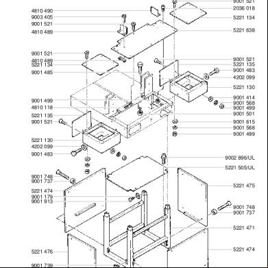
Ideal Guillotine Parts Manual 5221 95ep 1wr1i
December 2019 196
Service And Parts Manual Rexel Shredder Rds2050,rdx1750,rds2270,rdx1970 e5d1e
December 2019 139
Service And Parts Manual Rexel Shredder 1350-3250 Heavy Duty 5t4g6y
October 2021 0